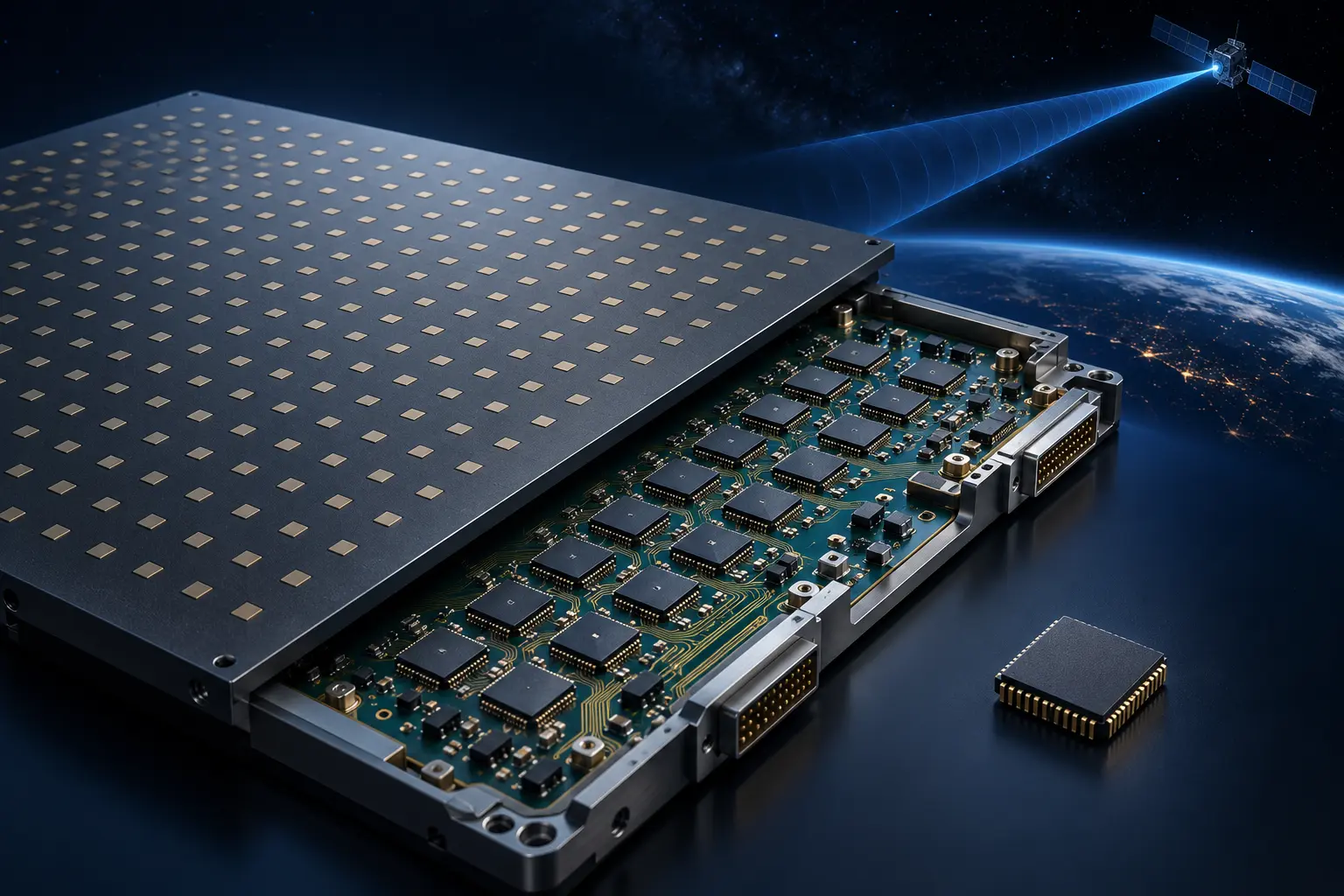
Concept rendering of a flat-panel phased-array antenna board populated with beamformer chips and a satellite link
From 5G to Satcom

Intelligence
behind
the beam.

Ka / Ku-band beamformer chips.
Connecting ground terminals to a world beyond.

RF EXPERTISE. REAL-WORLD TERMINAL FORMS.GROUND ↗ ORBITSCROLL TO EXPLORE ↓
BUILT AT THE INTERSECTION OF
Ka / KuSatellite frequency bands
BeamformingGround-terminal silicon
5G → SATCOMAn evolving RF foundation
01 / AIE chip lineup

Product Portfolio

Ka-band beamformers · ABF

AIEKA · TX

AIERWKA07

High TX PowerGEO ReadyHigh EIRP
View detailed specifications
SpecificationValue
TX Band27.5–31 GHz
TX Channels8
TX Gain23 dB
TX OP1dB17 dBm typical
TX Power280 mW/channel @ 17 dBm
Phase Control6-bit; 5.625° step; 360° range
Attenuator5-bit; 0.5 dB step; 15.5 dB range
Supply1.8 V / 2.5 V
Package4.4 × 4.9 mm FC-BGA
AIEKA · RX

AIERWKA06

Ultra-Low NFHigh G/TGEO Ready
View detailed specifications
SpecificationValue
RX Band17.7–21.2 GHz
RX Channels8
RX Gain25 dB typical
RX Noise Figure1.8 dB typ / 1.9 dB max
RX Input P1dB−38 dBm typical
RX Power320 mW all 8; 40 mW/ch avg
Phase Control6-bit; 5.625° step; 360° range
Attenuator5-bit; 0.5 dB step; 15.5 dB range
Supply / Package1.2 V RF; 2.5 V analog/digital; 4.4 × 4.9 mm FC-BGA

Ku-band beamformers and front ends · ABF / FEM

AIEKU · TDD

AIERWKU01

High RF PerformanceLow NFHigh TX Output
View detailed specifications
SpecificationRXTX
Band10.7–12.7 GHz14–14.5 GHz
RF Ports4 RX ports4 TX ports
Operating ModeTDD half-duplexTDD half-duplex
Gain21 dB typical27 dB typical
P1dBInput: −38 dBm typOutput: 11 dBm typ
Power40 mW/channel55 mW/channel
Phase Shifter6-bit; 5.625° step; 360° range6-bit; 5.625° step; 360° range
Attenuator6-bit; 0.5 dB step; 23.5 dB range6-bit; 0.5 dB step; 23.5 dB range
Package4.8 × 4.8 mm FC-BGA4.8 × 4.8 mm FC-BGA
AIEKU · 16CH

AIEMR11

16-Channel IntegrationLow PowerCost Effective
View detailed specifications
SpecificationRXTX
Band10.5–15 GHz10.5–15 GHz
Channels16 RX channels16 TX channels
Gain10 dB min / 12 dB typ (SPG)6 dB typ
Noise Figure10 dB / 12 dB max—
Power30 mW/channel30 mW/channel
Phase Control6-bit; 5.625° step; 360°6-bit; 5.625° step; 360°
Attenuator6-bit; 0.5 dB; 31.5 dB range6-bit; 0.5 dB; 31.5 dB range
Settling Time20 ns typical20 ns typical
Supply1.2 V RF/PA2.5 V analog/digital
Package6.8 × 7.8 mm FC-CSP, 186-pin6.8 × 7.8 mm FC-CSP, 186-pin
AIEKU · FEM

AIEMR1100

Ultra-Low NFHigh GainGEO Booster
View detailed specifications
SpecificationRXTX
Band10.5–13 GHz13–15 GHz
Channels2 bidirectional channels2 bidirectional channels
Gain29 dB typical32 dB typical
Noise Figure1.3 dB typical—
P1dBInput: −26 dBm typOutput: 10.5 dBm typ
Power20 mW/channel45 mW/channel
Switching40 ns min / 60 ns typ80 ns min / 100 ns typ
Supply1.6–2.0 V (1.8 V typ)1.6–2.0 V (1.8 V typ)
Package3.1 × 2.6 mm FC-CSP3.1 × 2.6 mm FC-CSP

RF transceivers and ADC / DAC

AIE8T/R · ADC

AIE8TRADC

Integrated RF TransceiverLow PowerMulti-chip Sync
View detailed specifications
Path / channelsRX · 8 channelsTX · 8 channels
RF band1.5–4.5 GHz1.9–4.5 GHz
ConverterSigma-delta ADC; up to 2 GSPS; 16× OS12-bit DAC; up to 500 MHz sample rate
Bandwidth1–100 MHz tunable; up to 100 MHz complex1–100 MHz channel bandwidth
Gain / outputRX gain 40 dBTX output 4 dBm
Noise / OIP3NF <15 dB; OIP3 35 dBmTX OIP3 15 dBm
Image rejection45 dBc50 dBc
Gain / attenuationRX gain range 40 dBTX attenuation 0–36 dB
LO leakage—≤−43 dBm @ 4 dBm output
Power / sync<0.13 W per active channel in FDD; multi-chip sync<0.13 W per active channel in FDD; multi-chip sync
Data interfaceJESD204B/C; up to 33 GbpsJESD204B/C; up to 33 Gbps
Package13 × 13 mm; 225-pin BGA13 × 13 mm; 225-pin BGA
AIE6881 · RF

AIE6881

Direct RF SamplingUltra-WidebandHigh Dynamic Range
View detailed specifications
SpecificationADC / RXDAC / TX
Converter8 × 14-bit; 4 GSPS8 × 14-bit; 12 GSPS
RF range10 MHz–6 GHz input10 MHz–6 GHz output
Instantaneous BWUp to 1.6 GHz complexUp to 1.6 GHz complex
Real-signal modeUp to 2 GHz; digital channel bypass2 channels; up to 6 GHz
Gain controlSHA fixed 6 dB; DSA 0 to −23.5 dB—
Clock / interface<50 fs RMS jitter; 60–750 MHz ref clockJESD204B/C; 4.15–33 Gbps SerDes
Power2.5 V / 1.3 V; <1 W, 1 RX + 1 TX full-power TDD2.5 V / 1.3 V; <1 W, 1 RX + 1 TX full-power TDD
Package25 × 25 mm BGA; 0.8 mm pitch25 × 25 mm BGA; 0.8 mm pitch

Digital beamformers · DBF

AIE6621 · DBF

AIE6621

High Beam DensityLow PowerRadiation Hard
View detailed specifications
SpecificationRXTX
Channels / beams128 / 128 @ ≤31.25 MSPS; 64 / 64 @ ≤62.5 MSPS96 / 32 @ ≤31.25 MSPS; 32 / 32 @ ≤62.5 MSPS
Sampling rate≤31.25 MSPS (128/128); ≤62.5 MSPS (64/64)≤31.25 MSPS (96/32); ≤62.5 MSPS (32/32)
Baseband / beam data12-bit input → 16-bit output12-bit input → 16-bit output
Interface / switchingJESD204B Subclass 1, ≤10 Gbps; LVDS/SPI; ping-pong <5 nsJESD204B Subclass 1, ≤10 Gbps; LVDS/SPI; ping-pong <5 ns
Radiation / packageTID 100 krad (Si); SEL 75 MeV·cm²/mg; 25 × 25 mm BGA, 900-pinTID 100 krad (Si); SEL 75 MeV·cm²/mg; 25 × 25 mm BGA, 900-pin
AIE6401 · DBF

AIE6401

High ThroughputTrue Time DelayRadar & SATCOM
View detailed specifications
SpecificationRXTX
Scaling8/8 @ ≤1,650; 16/16 @ ≤825; 32/32 @ ≤312.5; 64/64 @ ≤156.25 MSPS8 ch/4 beams @ ≤1,650; 16/4 @ ≤825 or 625; 32/4 @ ≤312.5; 64/4 @ ≤156.25 MSPS
Array / weightsNon-cascaded full RX: 16 / 16 @ ≤1,650 MSPS8/8 @ ≤1,650; 16/16 @ ≤825 or 625; 32/32 @ ≤312.5; 64/64 @ ≤156.25 MSPS
Bandwidth / method1.32 GHz @ 1.65 GSPSTrue time delay + complex weights
Switching / interface<5 ns; JESD204B/C GTA/GTS + control interface<5 ns; JESD204B/C GTA/GTS + control interface
Power / package1.0 V / 1.8 V / 2.0 V; 33 × 33 mm BGA, 1,024-pin1.0 V / 1.8 V / 2.0 V; 33 × 33 mm BGA, 1,024-pin

Wideband SDR transceiver

AIE6261 · SDR

AIE6261

Wideband SDRFrequency HoppingLow Power
View detailed specifications
SpecificationRXTX
Channels2 RX2 TX + 1 observation
Frequency30 MHz–7 GHz (TDD / FDD)30 MHz–7 GHz (TDD / FDD)
BandwidthTunable channel bandwidth 20 kHz–75 MHzTunable channel bandwidth 20 kHz–75 MHz
Gain / powerRX gain 30 dBOutput 5 dBm; attenuation 0–36 dB
Noise / OIP3NF 16 dB; OIP3 40 dBmOIP3 25 dBm
Image / leakageImage rejection 60 dBcImage rejection 60 dBc; LO leakage −60 dBm
Signal processing / LO / hoppingFractional-N PLL; external LO supported5 LO synthesizers; up to 40,000 hops/s
Power / package2.5 V / 1.3 V; <1 W (one RX + one TX, full-power TDD)2.5 V / 1.3 V; <1 W (one RX + one TX, full-power TDD)
InterfaceRBDP / LVDS data; SPI / GPIO controlRBDP / LVDS data; SPI / GPIO control
Package15 × 15 mm BGA, 289-pin15 × 15 mm BGA, 289-pin
02 / System architecture

Five Scenarios

1
ARCHITECTURE 1 · KA HIGH-END

GEO Gateway / Radar

Ka-band high-performance architecture

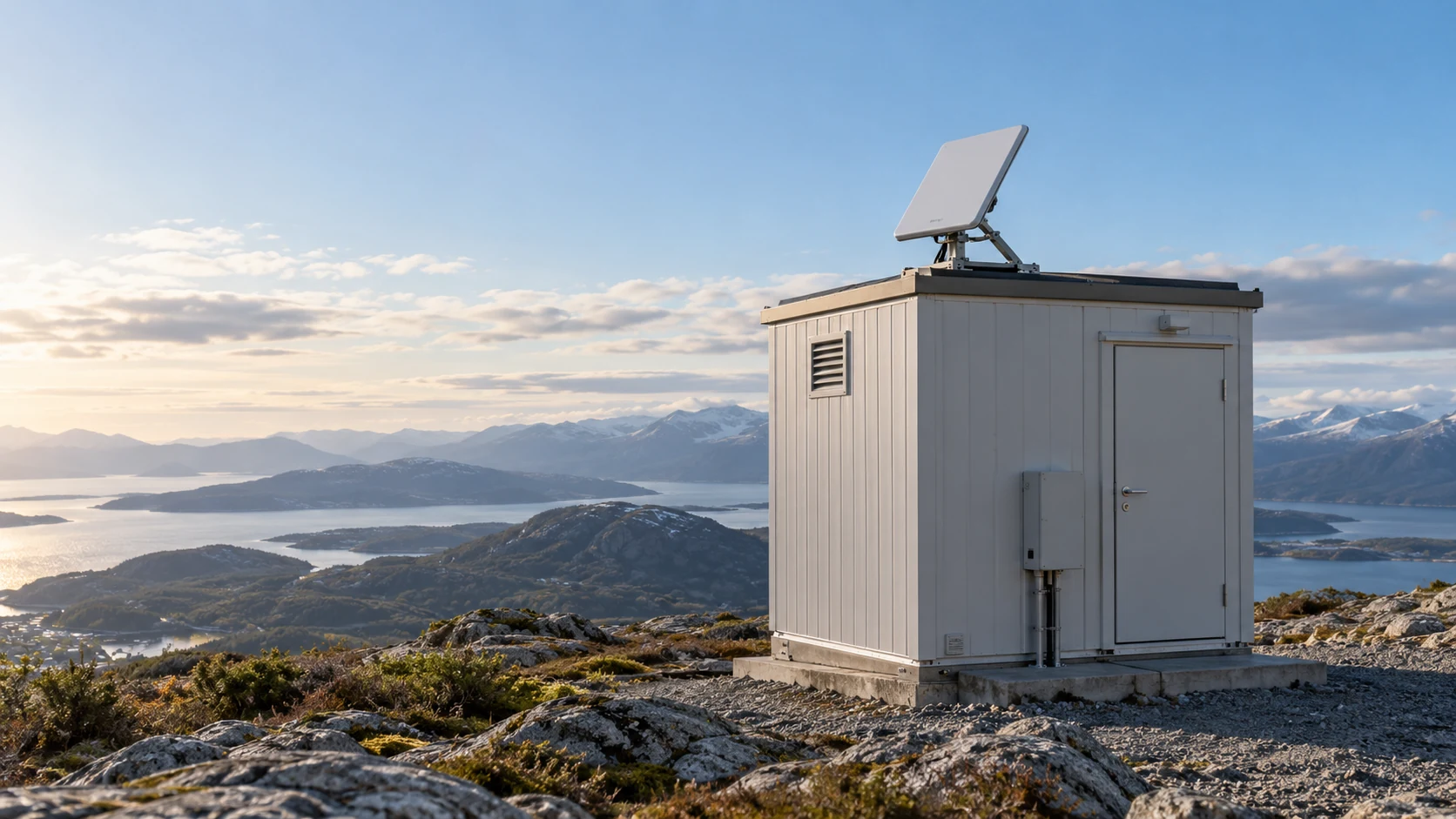
Fixed gateway concept with flat phased-array panels
Flat-panel gateway concept · concept rendering
IF YOU NEED

Ka Gateway, radar or ISR / EW systems that need the highest performance and wideband IF sampling.

Choose Architecture 1Open vertical signal chain & advantagesClose architecture details
Frequency bandTX: 27.5–31 GHzRX: 17.7–21.2 GHz

Architecture block diagram

  1. Antenna array
  2. AIERWKA07Ka TX ABF · 8 channels per IC; scale to arrayAIERWKA06Ka RX ABF · 8 channels per IC; scale to array
  3. UDC (up/down converter)Ka-band ↔ IF conversion required
  4. AIE68818-channel RF sampling ADC/DAC · 10 MHz–6 GHz
  5. AIE6401High-end DBF · 64 beams
  6. Baseband3rd party

Ideal Use Cases

GEO Gateway · Ka High Throughput · Radar / AESA · ISR / EW · Large Fixed Stations

Key Advantages

  • Direct sampling of ultra-wideband IF
  • Highest performance for Ka-band systems
  • Ideal for GEO Gateways, Radar & EW systems
  • Supports large arrays & high throughput
  • Best solution for mission-critical applications

Design check: AIE6881 samples the converted IF; its 10 MHz–6 GHz range does not cover Ka RF itself. Scale the 8-channel RF ICs and UDC paths to the array/subarray count. Confirm IF placement, AIE6881-to-AIE6401 lane/rate mapping, channelization and timing against both device configurations before freezing the design.

2
ARCHITECTURE 2 · KU NEXT GEN (LARGE ARRAY)

16-Channel Ku Solution · Mainstream Platform

Flat phased-array satellite terminal installed on a ship at sea
Shipboard flat-panel SATCOM concept · concept rendering
IF YOU NEED

Large arrays (512–2048 elements) for GEO / LEO / maritime / military SATCOM with a strong cost / performance balance.

Choose Architecture 2Open vertical signal chain & advantagesClose architecture details
Frequency bandTX: 13.0–15.0 GHzRX: 10.5–13.0 GHz

Architecture block diagram

  1. Antenna array
  2. AIEMR1100 × 8Ku 2-channel FEM · PA/LNA/TR switch
  3. AIEMR11Ku 16-channel TR BFIC
  4. UDCUp/down converter
  5. AIE8TRADC ×N8 RX + 8 TX paths per device; size N to channel topology
  6. AIE6621Mid-end DBF · RX 128 / TX 32 beams @ ≤31.25 MSPS
  7. Baseband3rd party

Ideal Use Cases

GEO User Terminal · LEO User Terminal · Maritime SATCOM · Military SATCOM · Large UAV SATCOM · Mobile SATCOM

Key Advantages

  • 16 TR channels with high integration
  • 75% fewer RF front-end ICs
  • Lower ADC & DBF requirements
  • Lower system power & smaller PCB area
  • Scalable from 256 to 2048 elements
  • Best cost / performance balance for large arrays
  • Ideal for GEO, LEO, Maritime & Military applications

Channel-count check: AIEMR1100 ×8 and AIEMR11 provide a 16-channel RF front end. AIE8TRADC has 8 RX + 8 TX paths per device; choose ×N from the required simultaneous independent paths and RF combining/splitting plan. Confirm the UDC presents an IF inside AIE8TRADC’s supported band, then validate ADC/DAC bandwidth, AIE6621 sample-rate/channel mapping and synchronization.

3
ARCHITECTURE 3 · KU COMPACT ARRAY

High-RF Performance Solution · Proven & Reliable

Unbranded commercial airplane with a flat phased-array panel concept
Commercial airplane flat-panel concept · concept rendering
IF YOU NEED

Compact arrays (64–256 elements) that need high RF performance and reliability.

Choose Architecture 3Open vertical signal chain & advantagesClose architecture details
Frequency bandTX: 14.0–14.5 GHzRX: 10.7–12.7 GHz

Architecture block diagram

  1. Antenna array
  2. AIERWKU01 ×NKu 4-channel TR per IC; scale to array/subarray
  3. UDCUp/down converter
  4. AIE8TRADC ×N8 RX + 8 TX paths per device; size N to channel topology
  5. AIE6621Mid-end DBF · RX 128 / TX 32 beams @ ≤31.25 MSPS · optional
  6. Baseband3rd party

Ideal Use Cases

Portable SATCOM · Vehicle Terminal · Commercial Airplane · Compact Flat Panel · Rapid Deployment

Key Advantages

  • High RF performance with high output power
  • Low noise figure & fast TX/RX switching
  • Mature technology with proven reliability
  • Easy system integration & low development risk
  • Ideal for compact arrays (64–256 elements)
  • Fast time-to-market for field-deployable systems

Aircraft TX/RX recommendation: Ask the aircraft integrator: “Must transmit and receive operate simultaneously, or is time-division (TDD) acceptable?” AIERWKU01 is specified as TDD half-duplex. If simultaneous TX/RX is required, use independent TX and RX paths with suitable duplex filtering and isolation; do not claim an external diplexer alone makes this TDD front end full-duplex. Validate isolation, coexistence, switching, EMC and aircraft qualification. If TDD is acceptable, confirm the timing plan and switching control.
4
ARCHITECTURE 4 · KU COST-OPTIMIZED

Front-End Only (No DBF) · Simple & Cost-Effective

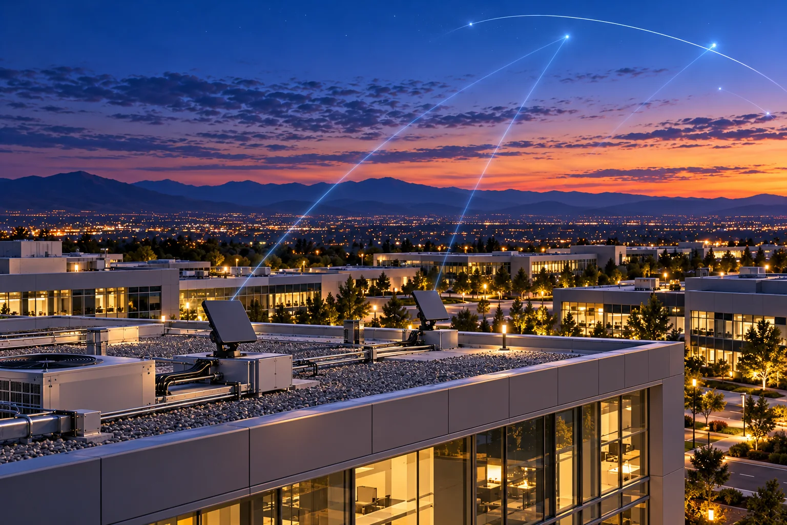
Original concept rendering of a compact fixed ground flat-panel satellite terminal
Fixed ground flat-panel terminal · original concept rendering
IF YOU NEED

The lowest-cost, simplest single-beam system without a DBF chip.

Choose Architecture 4Open vertical signal chain & advantagesClose architecture details
Frequency bandTX: 13.0–15.0 GHzRX: 10.5–13.0 GHz

Architecture block diagram

  1. Antenna array
  2. AIEMR1100 × 8Ku 2-channel FEM · PA/LNA/TR switch
  3. AIEMR11Ku 16-channel TR BFIC
  4. UDCUp/down converter
  5. AIE8TRADC ×N8 RX + 8 TX paths per device; size N to channel topology
  6. Customized BasebandCustomer supplied · single-beam processing
  7. Baseband3rd party

Ideal Use Cases

Low Cost VSAT · Point-to-Point Link · Monitoring / Telemetry · Single Beam Applications · Small Fixed Terminals

Key Advantages

  • Lowest system complexity & cost
  • 16 channel front-end with full integration
  • No DBF chip required
  • Lower power consumption
  • Ideal for single beam & cost-sensitive projects
  • Easy design-in & fast time-to-market

Channel-count check: The 16-channel front end does not imply one AIE8TRADC covers all paths. Select AIE8TRADC ×N for independently converted channels or document the approved analog combining/splitting topology. Confirm UDC IF range, converter bandwidth and baseband single-beam interface before sizing the BOM.

5
ARCHITECTURE 5 · WIDEBAND SDR / TACTICAL RADIO

30 MHz–7 GHz · SDR Communication Platform

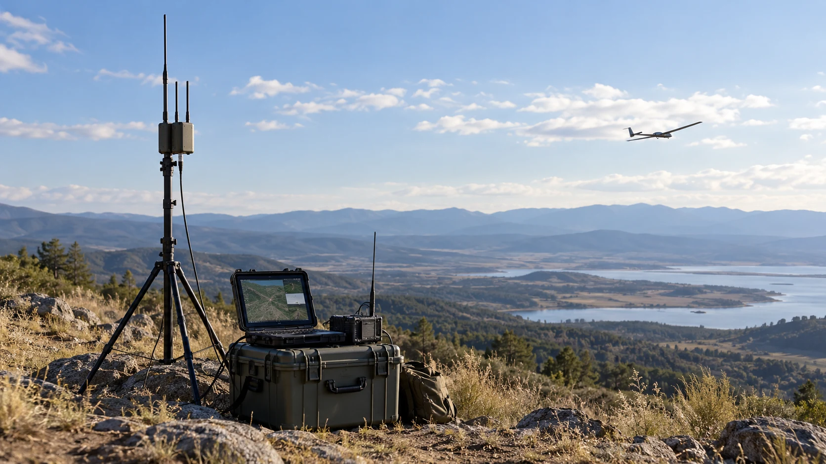
Original concept rendering of field SDR communications equipment linked to a small uncrewed aircraft
Wideband SDR field link · original concept rendering
IF YOU NEED

Wideband tactical radio / SDR communications from 30 MHz to 7 GHz.

Choose Architecture 5Open vertical signal chain & advantagesClose architecture details
Frequency bandTX / RX: 30 MHz–7 GHz (wideband)

Architecture block diagram

  1. Antenna
  2. AIE6261 ×N2 RX + 2 TX per IC · 30 MHz–7 GHz
  3. External FPGA / BridgeRBDP / LVDS ↔ JESD204B interface conversion
  4. AIE6621 DBF (optional)RX 128 / TX 32 beams @ ≤31.25 MSPS
  5. Baseband3rd party

Ideal Use Cases

Tactical Radio · Military SDR · UAV Data Link · UAV Swarm Comm. · Ground Comm. · Field Radio

Key Advantages

  • Wideband SDR from 30 MHz to 7 GHz
  • Dual RX + Dual TX
  • Frequency hopping & wideband communication
  • Low power & highly integrated
  • Ideal for tactical radio & SDR applications
  • Flexible platform for multi-mission use

Design check: The bridge is required between AIE6261 RBDP/LVDS and AIE6621 JESD204B. Size AIE6261/bridge resources to the number of simultaneous channels. Verify FPGA data mapping, clocking, timing and rate conversion against the chosen AIE6621 mode before committing to the optional DBF path.

Frequency bands, model names, use cases and advantage statements follow the supplied architecture graphic. System performance claims and all RF / digital interfaces remain subject to verification against the target configuration and chip datasheets.

03 / Technology advantages

High performance.
Lower system cost.

01

Low noise figure

Designed to preserve weak signals on the receive path.

02

Low power consumption

Efficient RF architecture for lower terminal power demand.

03

Strong price performance

Target pricing around 50% of mainstream comparable solutions.

04 / Application landscape

Flat-panel systems.
AIE silicon at the core.

05 / The AIE story

From 4G and 5G
to satellite links.

Years of RF development shape our next chapter in SATCOM: practical chip design, architecture and manufacturing collaboration.

ENGINEERING EXPERIENCE

Built through generations of wireless.

Our experience spans 4G and 5G development through to satellite communications. It covers RF chip design, system and architecture design, process integration and production planning. We work with our manufacturing ecosystem to support dependable access to production capacity.

4GRF foundations
5GBeamforming systems
SATCOMKa / Ku architectures
MANUFACTURING ECOSYSTEM

Designed for manufacturable scale.

Foundry support is primarily through STMicroelectronics and GlobalFoundries, aligned with process and production planning.

STMicroelectronicsGlobalFoundries
Engineering the next connection

Your next architecture.
Our next conversation.

Exploring a Ka- or Ku-band ground terminal? Contact AIE to discuss your architecture and integration requirements.

Product focus

Designed around AIE’s focus on satellite ground-terminal beamforming, spanning transmit and receive system architectures.

Discuss your operating band, array architecture, signal-chain requirements and integration targets with AIE. Detailed specifications and availability require confirmation.